
THERMOSTAT CONTROLLER Instruction Guide
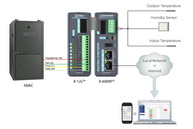
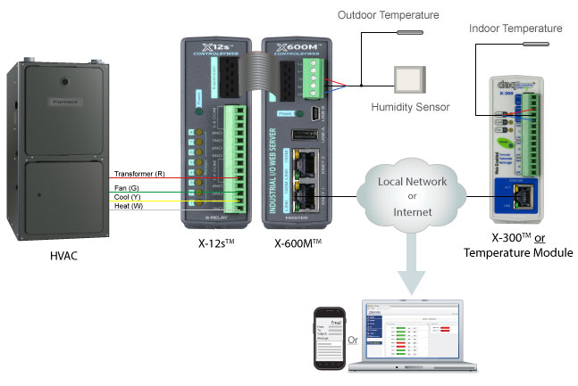
This application example illustrates how to use the X-600M as a thermostat to control an HVAC system. It is a full-featured single-stage thermostat with 7-Day scheduling for efficient operation. It can read indoor temperatures from a sensor connected directly to the X-600M, or it can read temperatures across the IP network from a sensor connected to an X-300 module (or other ControlByWeb device that supports Temperature/Humidity).
This example very closely emulates an X-300 module running in Thermostat Mode. The purpose of this example is not to show how to make the X-600M become a more expensive replacement for the X-300, rather, it is to use as a basis for custom thermostat functions. For example, users can take the basic functionality of the X-300 and customize it to meet specific needs. This functionality could also be duplicated inside the X-600M to function as multiple thermostats to control multiple HVAC systems or zones.
EQUIPMENT NEEDED
- 1 – X-600M™
- 1 – X-12s 8-Relay Expansion Module™
- 1 – Expansion Cable
- 2 – 1-Wire Temperature Sensors
- 1 – Humidity Sensors
- 1 – Thermostat Controller Software Package (.zip)
- 1 – Ethernet cable
- 1 – 9-28V Power Supply (24V recommended)
- Pre-installed HVAC system
- Optional: X-300 (in temperature monitoring mode) or a Temperature Module for remote temperature readings
X-600M Thermostat Controller
X-600M Thermostat Controller with a remote temperature sensor
THERMOSTAT CONTROLLER INSTRUCTIONS
STEP 1: Basic Setup and Wiring
Begin by connecting a 9-28V power supply (24V power supply recommended) to the Vin+ and Vin- terminals on the X-600M (A regulated power supply is recommended). Verify that the power supply is rated for the operating current of the X-600M. (For more information see Section 2.3.2 of the X-600M User’s Manual).
Connect one of the Ethernet ports to a 10 Base-T or 10/100 Base-T Ethernet connection. Typically an Ethernet hub, switch, or router. (For more information see Section 2.3.6 of the X-600M User’s Manual).
Connect heating signal to 1NO on the X-12s and power to the common contact COM 1-4. Whenever the thermostat calls for heat, Relay 1 is turned on. If a separate fan connection is required, connect it to 3NO on the X-12s.
Connect the cooling signal to 2NO. The fan control signal is connected to 3NO. Relays 2 and 3 are turned on when the thermostat calls for cool and fan respectively.
For the 1-wire sensors, connect all three (Two temperature and one humidity) sensors to the X-600M terminal block, with the +5V, Dat, and Gnd in their respective terminals.
NOTE: Be sure that all the connections to any of the devices are clean and don’t have the possibility of shorting out, and that all the screws are tight.
STEP 2: Adding/Configuring I/O
Access the X-600M setup pages by typing its IP address into the address bar of your internet browser followed by /setup.html (i.e., 192.168.1.2/setup.html). Log into the setup pages (default user name: admin, password: webrelay) and navigate to the System > Backup/Restore menu tab. (For more information see Section 3.3 of the X-600M User’s Manual).
Click the Choose File button and navigate to the thermostatSettings.bak file included in the Thermostat Software Package. Now click the Import button and wait for the process to finish. When it has finished scanning the expansion bus, you will be asked to select the address of the X-12s you would like to use. Simply drag the address from the list on the leftover top of the address in the list on the right.
After the X-12s serial number has been updated, you will also need to update the 1-Wire sensor addresses. To do this, navigate to the I/O tab and then 1-Wire Sensors and click the Edit button for the outTemp sensor. From the edit window, choose the appropriate sensor number from the drop-down menu and click Update. If the address is not shown, you will need to verify the wiring and click the Scan 1-Wire Bus button. If you are unsure which sensor number corresponds with which sensor device, disconnect all the sensors from the X-600M and add them one at a time. Once the outTemp has been updated, update the curTemp and curHumidity sensor numbers using this same method.
Next you will want to set the IP address of the X-600M to what you would like it to be. When the settings are loaded, they will restore the IP address used in the settings file, but they will not take effect until the changes are committed. Set the IP settings and click Submit, and then click Commit Changes.
If your configuration uses 1-Wire sensors connected to the X-600M, you may skip to the next section. The remaining paragraphs of this section will explain how to use remote temperature sensors with this thermostat application. We will use an X-300, but you can use any ControlByWeb product that supports temperature/humidity sensors. We will assume that the X-300 has already been assigned an IP address and is on the same network as the X-600M.
Connect the temperature and humidity sensors to an X-300, as explained in the X-300 users manual. For the X-300, please note that you will want it to be in Temperature Monitoring mode. Once the wires have been connected, you will need to configure them on the device they are attached to. For example, you will need to assign the sensor address to a sensor number in the X-300’s setup page by clicking the Sensors tab. Select Sensor1 from the drop-down list, choose the address that corresponds to the indoor temperature sensor and then click Submit. Repeat this to assign Sensor2 as the outdoor temperature and Sensor3 as the humidity, if desired.
Once the X-300 has been configured, you will need to log onto the X-600M’s setup page, and click the Devices tab, then the Find New Devices button and wait for the scan to complete. When the scan completes, you should see the X-300 you recently set up. Click the Add button and add the first three temperature sensors as I/O to the X-600M.
Navigate to the I/O tab and click 1-Wire Sensors and edit the three temperature sensors listed by clicking the Edit button, and from the Device pull-down menu, select the X-300. Once the page has finished loading, select which sensor number on the X-300 corresponds with the sensor on the X-600M you are currently editing. Once all three sensors have been updated, click Commit Changes.
STEP 3: Custom Web Pages
We have created some customized web pages for this application that make it easier to setup and use once it has been configured. We will need to load those pages onto the X-600M.
Navigate to the System tab, and then choose Custom Web Pages in the sub-menu. In the upper right-hand corner click Choose Files. This will open a dialog box, where you can navigate to the folder on your computer where you have saved the custom web pages.
Select all of the pages and graphics for the Thermostat, and click Open. Then click the Upload File(s) button. The X-600M will update the list of custom pages, and you should be able to see the pages that you have just added.
To setup the thermostat, click on the file called thermoSetup.html from the list shown in the X-600M. From here, you will be able to program the schedule as well as view the thermostat.
STEP 4: Thermostat Page
To access the thermostat add after the IP address of your X-600M in the address bar of your web browser (i.e., 192.168.1.2/thermostat.html). This is the main page for manual control of your Thermostat and it also displays the current state of your HVAC system. Across the top you can see the state of the following:

When these images are visible it indicates that the corresponding feature is on. Below these images, you can see where the current temperature and set temperature are displayed. When the 7-Day Programming is running the set temperature will not correspond to the current control temperature. The buttons on the right of the set temperature allow you to adjust the control temperature. When these buttons are used while the 7-Day Programming is running the programming will be overridden.
Below the temperatures, there are the heat and fan mode controls. This allows you to set which mode the thermostat will be running in. Below that we can see the current humidity, and below that we have the Reset Filter, and Hold buttons. The reset filter button will reset the countdown for the filter change. This requires the device to Commit Changes. The hold button will pause the 7-Day schedule on its current settings, without updating until the hold has been turned off. This button however doesn’t affect manual control. Below these controls, you will see the filter countdown.
The outdoor section of the Thermostat first displays the current outdoor temperature. Below that it will keep statistics of today’s and yesterday’s high and low temperatures, as well as what time those temperatures were reached. This information is reset whenever the unit is powered off.
STEP 5: Setup Page
To access the setup pages of the Thermostat add /thermoSetup.html after the IP address of your X-600M in the address bar of your browser (i.e.,192.168.1.2/thermoSetup.html). You will then be able to access the different setup pages using the menu across the top.
Thermostat Setup
On the Thermostat Setup page you will find important values that need to be set so that your thermostat will run correctly. The following values are located on this page:
| Min Cycle Time | The time specified in this field (in minutes) is the minimum time that the HVAC system will run, even if the set point is reached. It is also the minimum time that the HVAC system will remain off. This prevents HVAC turning on an off too frequently. This field can be set within the range of 2 to 15 minutes. |
| Global Max Set Temp | This is the maximum temperature that can be set by the user in the 7-Day Program. |
| Global Min Set Temp | This is the minimum temperature that can be set by the user in the 7-Day Program page. |
| Manual Max Set Temp | This is the maximum temperature that can be set by the user in the Thermostat page. |
| Manual Min Set Temp | This is the minimum temperature that can be set by the user in the Thermostat page. |
| Heat Anticipation | When a heating system heats a building, the temperature rises until it reaches the desired temperature and the thermostat shuts off the heat. Due to thermal inertia, the temperature may continue to rise and over-shoot the set temperature after the heat is turned off. The Thermostat can be set to anticipate the overshoot and turn off the heat slightly before the set temperature is reached to reduce the over-shoot. The Thermostat will turn off the call for heat at the set temperature minus the value entered in this field. This value can range from 0 to 20. |
| Cool Anticipation | This works similar to heat anticipation. The Thermostat will turn off the call for cool at the set temperature plus the value entered in this field. This value can range from 0 to 20. |
| Fan On With Heat | Many heating systems will automatically turn on the fan as they heat. Some systems require that the thermostat turn on the fan and heat simultaneously. When this box is checked the Thermostat turns on the fan (Relay 3) when it turns on the heat (Relay 1). Otherwise Thermostat does not turn on the fan when it turns on the heat (this is the correct setting for most systems). |
| Fan Shut-Off Delay | The time specified in this field (in seconds) is the amount of time that the Fan will continue to run after the set temperature is reached, and the minimum cycle time is expired. This field can be set within the range of 0 to 600 seconds. |
| Email Notifications | When this box is checked, the Thermostat will send email messages to the email recipients listed under the admin group whenever the indoor air temperature exceeds the High Temp Email setting, falls below the Low Temp Email setting, or when the Filter Change Period reaches 0 days. |
| High Temp Email | This is the high temperature threshold for sending email messages. When the indoor air temperature reaches this value, notification email messages will be sent if email is properly set up and Notification Email setting is checked. |
| Low Temp Email | This is the high-temperature threshold for sending email messages. When the indoor air temperature reaches this value, notification email messages will be sent if email is properly set up and Notification Email setting is checked. |
| Filter Change Period | The Thermostat provides a reminder to change HVAC system filters. The number of days between filter changes is entered here. When the reset filter button is pressed, a counter will be set with this value. Each day, the counter will decrement by one. When the counter gets to zero, a filter change notice will appear on the Thermostat View page and an email message will be sent (if enabled). Once the filter change period expires, the user can reset the counter on the Thermostat View page. Note that each time the Filter Reset button is pushed settings will be committed. |
7-Day Programming
The Thermostat allows you to specify the seven-day temperature schedule. Temperatures can be set to change up to four times each day. Note that for each set time, two temperatures (a heat temperature and a cool temperature) can be specified. When the Thermostat is operating in Heat mode, the listed Heat set temperature will be used. When the Thermostat is operating in cool mode, the listed Cool set temperature will be used. When the Thermostat is operating in automatic mode, it will use the listed Heat set temp whenever it heats the building and the listed Cool set temp whenever it cools the building.
The cool temperature must be set at least 3 degrees Fahrenheit (1.5 degrees Celsius) higher than the heat temperature. To change a setting, click the desired time period from the calendar. A pop-up box appears. Enter the time at which this period will start (in 24-hour time) and temperatures in the option box. Note that to make a change for the entire week at a specified time period, the far left-hand columns, labeled Morning, Afternoon, etc., may be selected. Be sure to Commit Changes so that your settings will take effect.
HOW IT WORKS
Scripts
The LUA scripts are the heart of the logic behind this thermostat. The first script will control various functions of the thermostat. It is called script1 and can be viewed by navigating to Control/Logic > Scripts and clicking on the Edit button. We will look at an overview of the comments in the code so we can understand what is happening.
The script begins by starting an infinite loop.
–Update High and Low values as they change
Here the code will check if the current outdoor temperature value is higher or lower than the high and low stored respectively, and if they are it will change the corresponding value.
–Send Email Alerts
In this part of the code, the unit checks if email alerts are turned on, and then it will send the email alert based on the high and low-temperature alarms, and the current filter status.
–Sets the high and low values on power up
Whenever the unit loses power, the high and low-temperature information is lost and therefore needs to be loaded, which happens in this part of the code. The unit will check if both values are defaulted, then it will set the values to the current temperature and time.
The second script, “script2” controls the HVAC logic. We will look at the comments, and give a short description of what is going on.
–HVAC control logic
The script begins by initializing the variables and then starting the loop.
–Manual Control
Here the script checks to see if it is in manual control mode either because the 7-Day Programming is turned off, or because it has been overridden from the thermostat page.
–OFF
If the unit is set to off, it will make sure that all the relays stay off.
–HEAT
If the unit is set to heat on, it will turn on the heat when the temperature is 2 degrees less than the value set on the thermostat page. Then when the temperature has passed above the set temperature adjusted for heat anticipation, and has been on longer than the minimum cycle time it will turn the heater off.
–COOL
If the unit is set to cool on, it will turn on the cooler when the temperature is 2 degrees greater than the value in the set on the thermostat page. Then when the temperature has passed below the set temperature adjusted for cool anticipation, and has been on longer than the minimum cycle time it will turn the cooler off.
–AUTO
If the unit is set to auto it will use a combination of the above logic to run the heater when the temperature is too low, or the cooler when the temperature is to high.
–7 Day Programming Control
The logic here will be the same as what is used in the manual control section, but it will use the “setHeat” and “setCool” temperatures instead of the “setTemp” value.
–Minimum cycle time
In this part of the code we check to see if either the heat or the cool came on, and if it did we set a flag and take note of the time. Then we compare the start time subtract the current time with the minimum cycle time, and when it is greater we set the flag to 2 letting the logic up above know that it is okay to turn the heat/cool off if necessary.
–Fan mode
Here we find the logic for running the fan. It will check if it is supposed to come on with the heat and cool, and then when the heat or cool goes off it will wait for the amount of time set by “fanOnTime”, and will then turn off.
Registers
The LUA scripts interact with the custom web pages and vice-verse through registers. Below is a brief description of each of the registers and their function.
| setTemp | Current set temperature to maintain |
| heatMode | Determines what mode the system is in (OFF/HEAT/COOL/AUTO) |
| fanMode | Behavior of the fan relay (AUTO/ON) |
| hold | Controlled from the thermostat page and checked by the actions before changing the set temps according to the 7-day schedule. |
| day7 | Controls whether the system goes according to the 7-day schedule or not. |
| minCycleTime | Minimum time the HVAC should be in any state |
| globalMax | Maximum temperature the system should ever allow for a set point |
| globalMin | Minimum temperature the system should ever allow for a set point |
| manualMax | Maximum temperature the thermostat will allow for manually changing the set point |
| manualMin | Minimum temperature the thermostat will allow for manually changing the set point |
| heatAnticipation | Number of degrees below the set-point to turn off the heat |
| coolAnticipation | Number of degrees above the set-point to turn off the cooling |
| fanWithHeat | Determines if the fan should run with the heat |
| fanOffDelay | How long after the cooling or heating (if fanWithHeat desired) turns off before the fan should turn off |
| Indicator if the system should send emails on temperature alarms and when the filter expires | |
| hTempAlarm | High alarm threshold for email alerts |
| lTempAlarm | Low alarm threshold for email alerts |
| filterChange | |
| yesterdayHigh | Yesterday’s outside high temperature |
| yesterdayLow | Yesterday’s outside low temperature |
| todayHigh | Today’s outside high temperature |
| todayLow | Today’s outside low temperature |
| setHeat | Heat set point for the 7-day schedule |
| setCool | Cool set point for the 7-day schedule |
| todayHighTime | Time the outside high temperature occurred today |
| todayLowTime | Time the outside low temperature occurred today |
| yesterdayHighTime | Time the outside high temperature occurred yesterday |
| yesterdayLowTime | Time the outside low temperature occurred yesterday |
| override | Allows the 7-day schedule to be overridden |
Calendar Events
The calendar events enable us to have a 7-day schedule with unique set points. Each of the calendar event times happen according to how they were configured on the Thermostat Setup page. That custom web page will change the times of the event and effectively change the time the action to change the set point runs.
Aside from the set point events, there are two others called midnight and resetFilter. The midnight event triggers an action to change the highs and lows for today and yesterday. The resetFilter event indicates when the air filter in the HVAC system needs to be reset.
Actions
All but one of the actions are dynamically created and modified. The set points in the 7-day programming generate an action to set the temperatures for the particular time period. These actions are triggered by the calendar events.
The last action (changeTemps) rotates the highs and lows for today and yesterday. This is triggered by a calendar event that runs every night at midnight.
Web Pages
The custom web pages rely on JavaScript, the included x600 library, and the Smarty Template Engine to make things work. As you can see in the HTML files, the Smart Template Engine can populate some information about the IO, registers, events, and actions. The x600 JavaScript library has the functions needed to periodically update the values on the HTML.
The JavaScript has been commented and it is recommended to review those code files while referencing the X-600M users manual (Appendix: H Custom Web Pages).